Connecting Pages
To connect pieces of spaper (pages) together, simply connect one symbol to two different pages.
Typically, one would use a wyre2 for this. Please
note that without an explicit connection, pages do not
connect in any way. For instance, GND, VCC, A, B, C, and D are not
automatically connected, and neither are adjacents.
Comments
All symbols may be written on with either dry erase or permanent marker. Useful for comments or labeling nets. Be sure to let permanent marker dry thoroughly.
aww-9
Summary
The standard Schematic Paper architecture is called aww-9.
Pinout
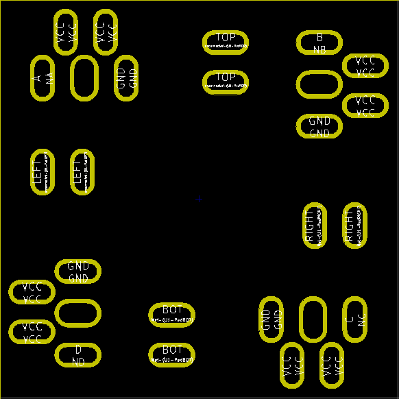
The pinout of aww-9 is shown here. The yellow circles indicate plated slots. There are two system nets, VCC and GND. There are four user nets, A, B, C, and D (labeled NA, NB, NC, and ND). Finally, there are four adjacents (that connect to the symbol above, left, right, and bottom respectively). The holes without any label do nothing. Please note that these holes may be damaged. It doesn’t affect the function of the Spaper.
Fixing Broken Connectors
When a connector is broken, oftentimes it can be repaired. This may take some practice.
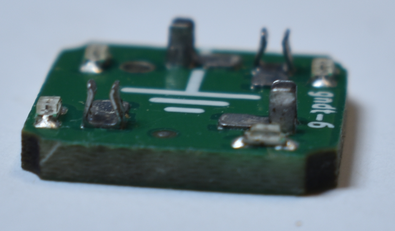
Connectors should look like this. If not, they may need repair.
Peeled Pads
You may repair connectors unless the pad has been lifted. This symbol cannot be repaired.
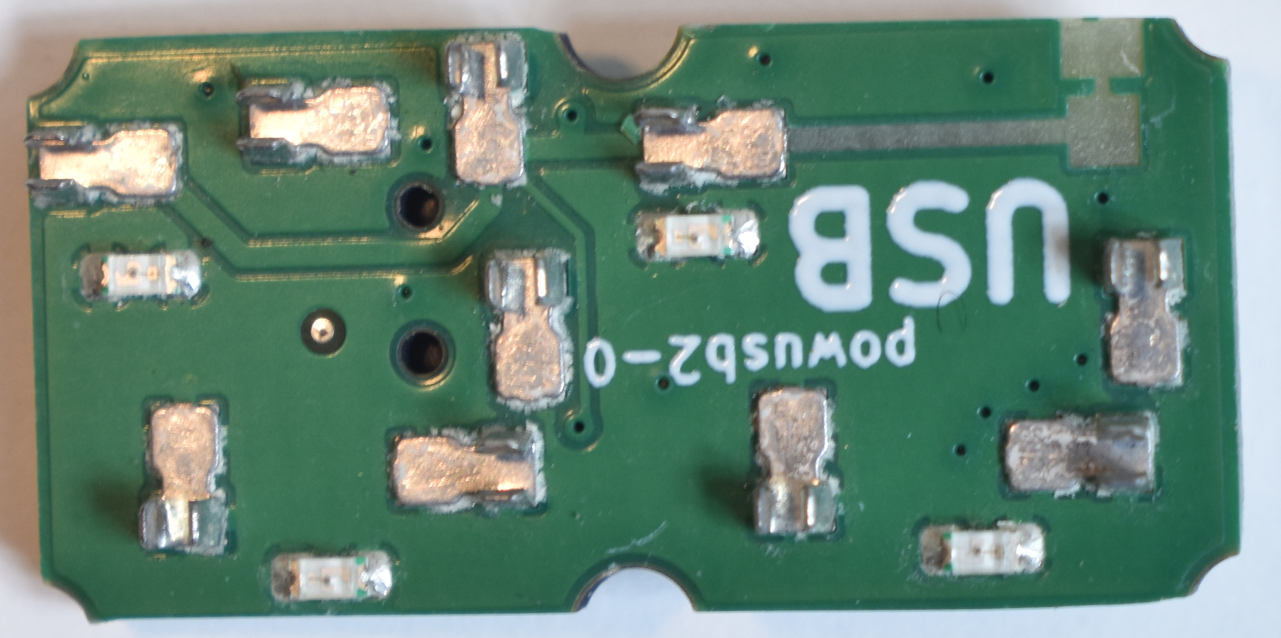
If the symbol functions as normal, that connector may be redundant or may just be for shielding. This is the case with the symbol above.
If a symbol is fully functional, but has a defect, mark with a blue permanent marker. Pictured symbol has some additional manufacturing defects.
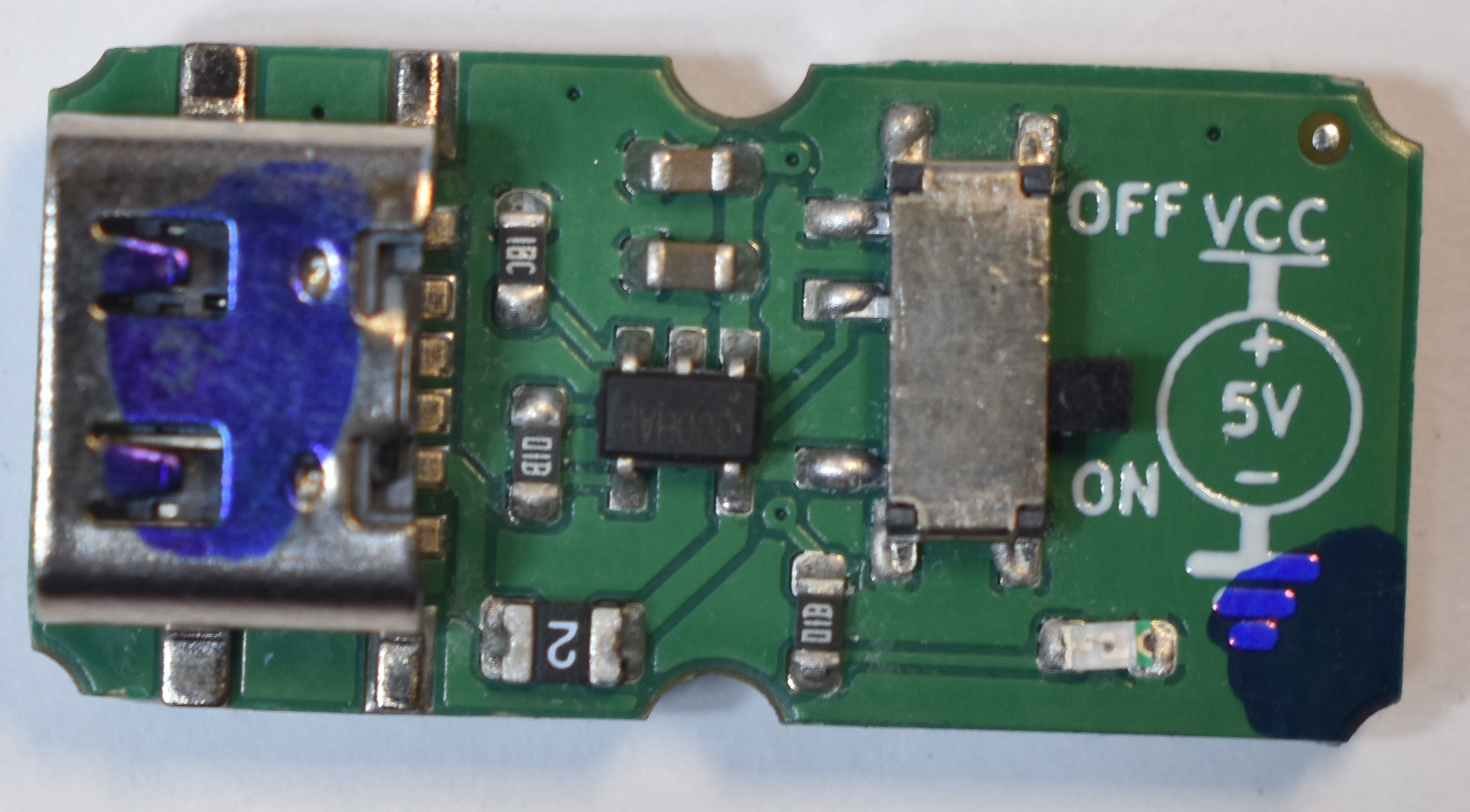
Mark both top and bottom. Makes it significantly easier to identify.
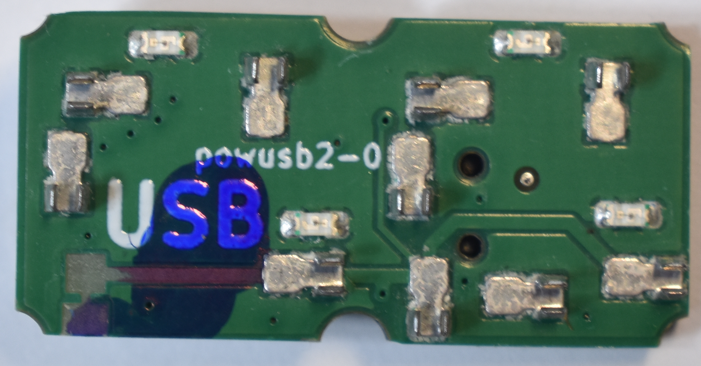
If a symbol partially functions, don't use it, repair it, or mark it with a red permanent marker.
Lost Connector
Sometimes, connectors aren’t soldered entirely. They could fall off. This is due to a known manufacturing defect.
In cases such as these, the symbol is easily repairable.
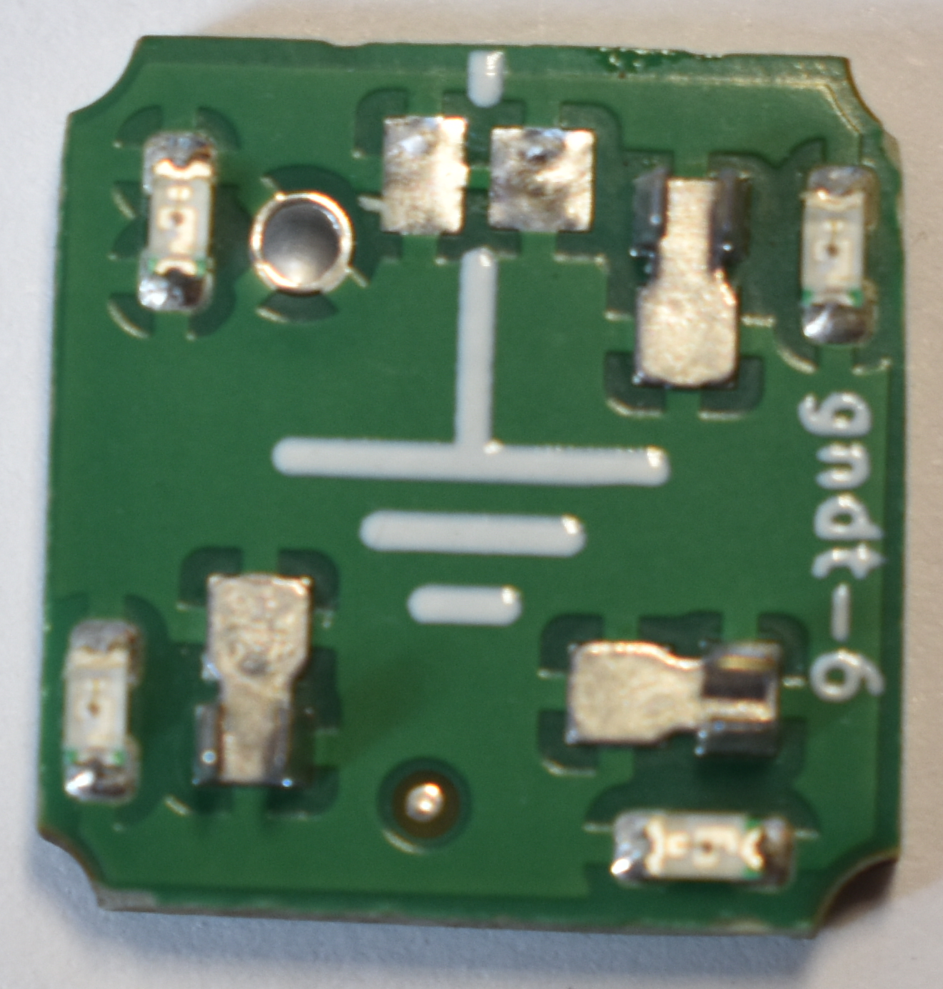
Before attempting to repair, it’s recommended to clamp the symbol. Clamp by the sides. Preferably ase a clamp that can withstand soldering temperatures. Place the clamp on a heat resistant surface.
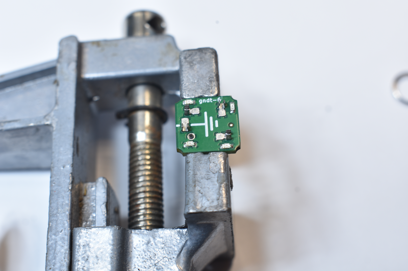
First, ensure the pad has a small amount of solder, yet still complete coverage. The amount of solder is important. Do not use too much or too little. Use any method you’d like, including solder paste.
Next, apply flux.
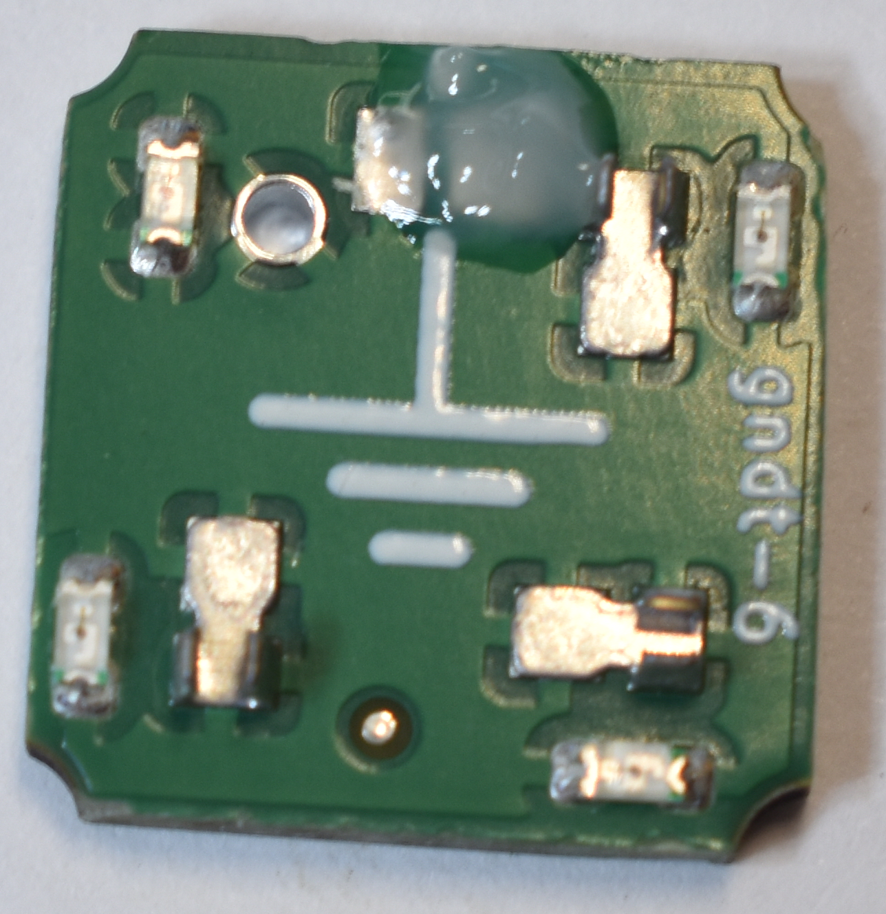
The position of the connector can be determined by the footprint. This is an example of a bare pad.
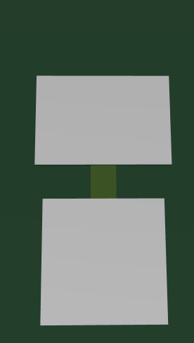
The bare pad with connector installed correctly.
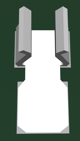
Place the connector. Does not need to be exact before you solder it.
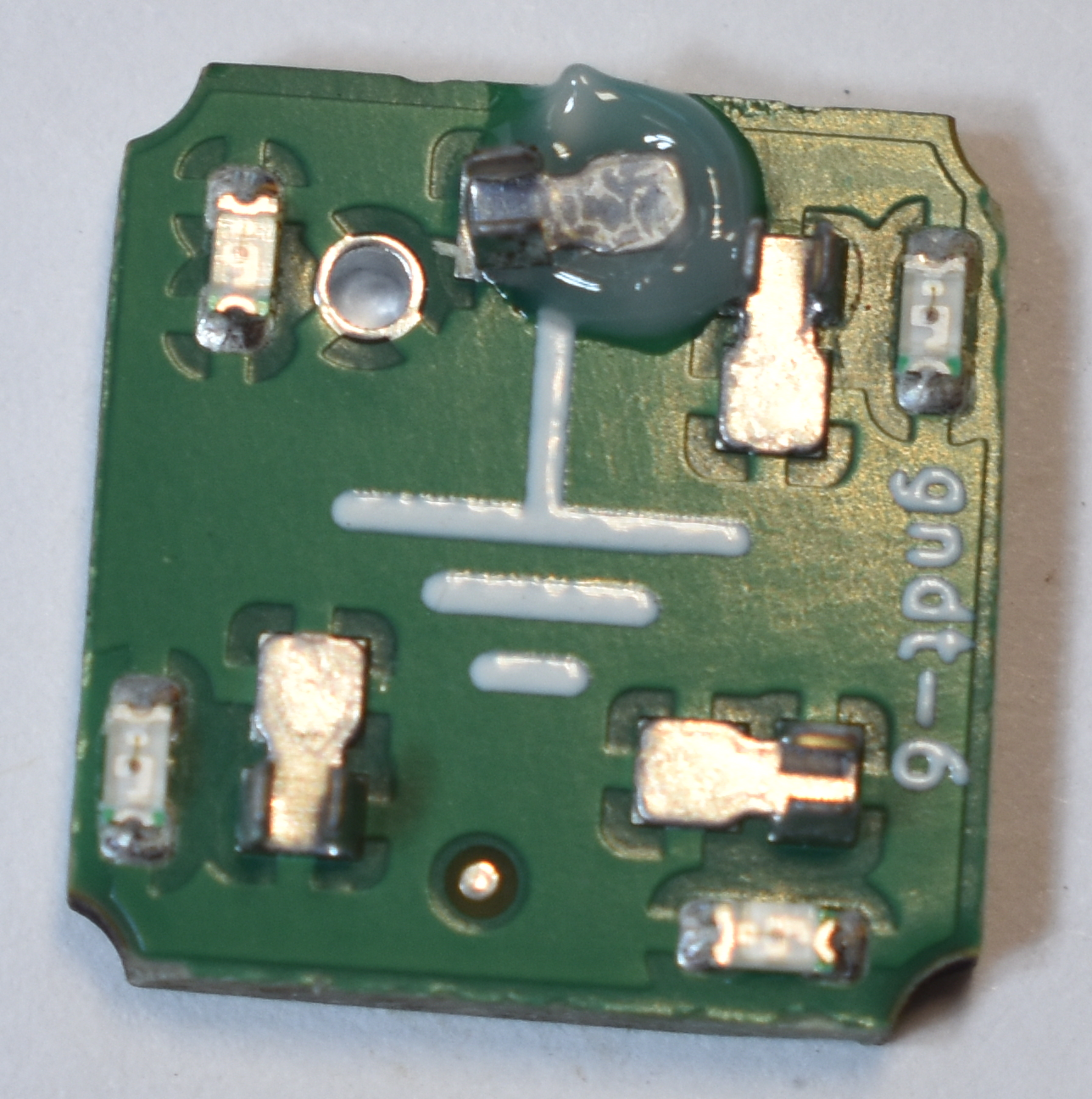
Heat up symbol with a hot air gun. Use tweezers to gently nudge the connector into place. Ensure complete coverage of the footprint.
If the proper amount of flux is used, the connector automatically snaps into place.
Ensure the connector is straight and very precisely placed.
Do not get solder on top of the connector anywhere.
This is what it should look like directly after soldering.
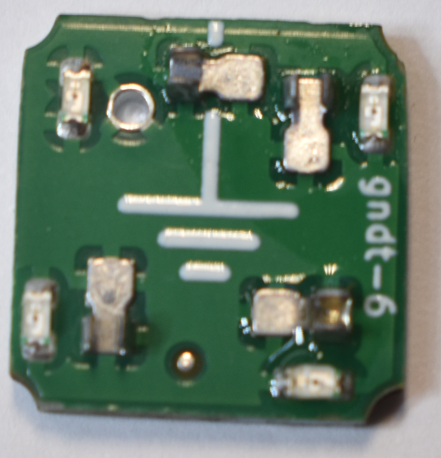
Next clean the symbol with IPA and a (preferably) ESD safe brush. Dip the brush in plenty of IPA. Scrub it a bit, then immediately blot up the IPA with a (preferably) lint free tissue. Repeat these steps until the symbol is clean. Or, just use a ultrasonic cleaner.
Do not use an ultrasonic cleaner with symbols that have parts that IPA could enter, such as potentiometers and switches. We learned this the hard way. The dissolved flux gets into the part and it gets gummed up, then break.
After cleaning, symbols look like this.
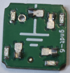
Bent Connectors
Most commonly, connectors get bent by improper use.
Dangerously Bent Connectors
If the connector is bent inwards in this manner, it likely needs to be replaced. There’s a risk of lifting the pad in these cases.
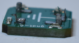
Another angle of the bent connector shown below. Clamp and use a hot air gun with tweezers to remove the connector. Then, follow the steps for lost connectors.
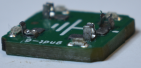
Normally Bent Connectors
If the connector is bent as shown, it can probably be bent back to how it was.
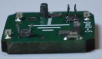
Start by using tweezers to bend the connector together.
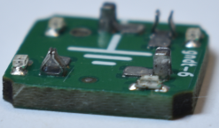
Next, insert a Gridwrench into the connector.
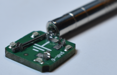
Pull the Gridwrench upwards through the connector. The connector is now repaired.
It is highly recommended to use a proper Gridwrench. The standard 1mm removal tool doesn’t work too well for this. Really, you could just tweeze the connector together without a gridwrench at all, with some practice.
Testing Symbols
After repair, install the symbol into a circuit. It should insert easily. While testing the circuit, gently bend the Spaper in a few directions. Repeat while wiggling the symbol. If the circuit continues to work, the symbol is repaired. This is an important step-- the last thing you want is a symbol that works sometimes.
Glossary
Orientation
The rotation of a symbol.
Pin
Essentially all electronics are created by connecting different "components" together. Each one of these components has one or more pieces of metal sticking out-- these are called "pins".
Pinout
What pin means what.
Oriented Symbol
A symbols that requires a specific rotation. Oriented symbols on the same page "must" be oriented in the same way. In reality, there are advanced techniques concerning incorrect orientation.
Net
A net is a piece metal accessible by all symbols. If two different symbols connect to VCC, they are connecting to the same net. Nets are split up into two categories, User Nets and System Nets.
User Net
A net that may be used in any way. Each is assigned a letter. The standard Schemaitc Paper page has four user nets. These are A, B, C, and D.
System Net
A net with a specific function dictated by the Spaper authors. The standard page has two System Nets, GND and VCC.
Adjacent
A connection to an adjacent symbol.
Want More?
Contact us at all@circuitplaytime.com .
Thanks
From us at Circuit Playtime, we really hope you have fun!